All iec 61131-3 ladder logic symbols Symbols used in plc programming । ladder logic diagram symbols । how to Plc block diagram
What is the Difference between Ladder Logic and Function Block Diagrams
Plc programmable diagrams Step function block diagram complete wiring schemas Plc diagram block functional plcs know afraid wanted ask everything were but systems where used
Fbd bloques block function funciones lenguaje langage schneider linguaggio réseaux sprache netzwerke ld
Plc block fbd program examplePlc block diagram functional basics Plc block diagram basicsPlc learning series 7: functional block diagram program, symbols.
Logix plc programming fbd language intro confident continuing becoming towardBlock function logic ladder diagrams between difference Plc wiring diagram symbols collectionPlc logic programmable controller components.

Plc programming block function example ld not manual ald contact
Intro to function block diagramCounter plc using a functional block diagram Plc programmingPlc diagram block.
Plc diagram block system control simplified parts main containControls create custom block plc diagram functional counter using graphically way very use [explained] plc block diagramWhat is the difference between ladder logic and function block diagrams.

Plc controller automation heating
Architecture of plc with block diagram – plc tutorial pointPlc symbols logic ladder Plc learning series 7: functional block diagram program, symbolsPlc experion programming code for flc as functional block diagram.
Functional plc fbdPlc (programmable logic controller): block diagram plc How to read a plc schematic « (2023)Block plc diagram logic controller programmable.

Function block diagrams
Program plc di sekolahWhat are user defined function blocks in plc? Plc diagram block logic input output programmable module controller control modules programming cpu unit processing notesFbd-sprache (funktionsbausteindiagramm, function block diagram).
Programmable logic controller (plc) componentsWhat is plc block diagram? plc working cycle Diagram wiring plc block programming symbols 0aa0 module board di data dc cdPlc ( programmable logic controller ) : introduction, use, example with.

Ebook: automating manufacturing systems; with plcs
Block diagram of a plc systemPlc functional block diagram basics Everything you wanted to know about plcs but were afraid to ask️plc wiring diagram symbols free download| gambr.co.
Block diagram of plc systemBlock diagram of plc Block diagram of plcPlc symbols schematic electrical wiring plcs diagrams jic figure.

Plc explanation
Plc fbd block diagram functional language programming automation industrialIndustrial automation : plc programming language Ladder symbols logic iec plc cheatIntroduction to function block programming in rslogix 5000.
.


PLC Block Diagram Basics | PLC Function Blocks Explanation | PLC Basics

Everything You Wanted To Know About PLCs But Were Afraid To Ask | PLC

Block Diagram of a PLC System - Your Desk
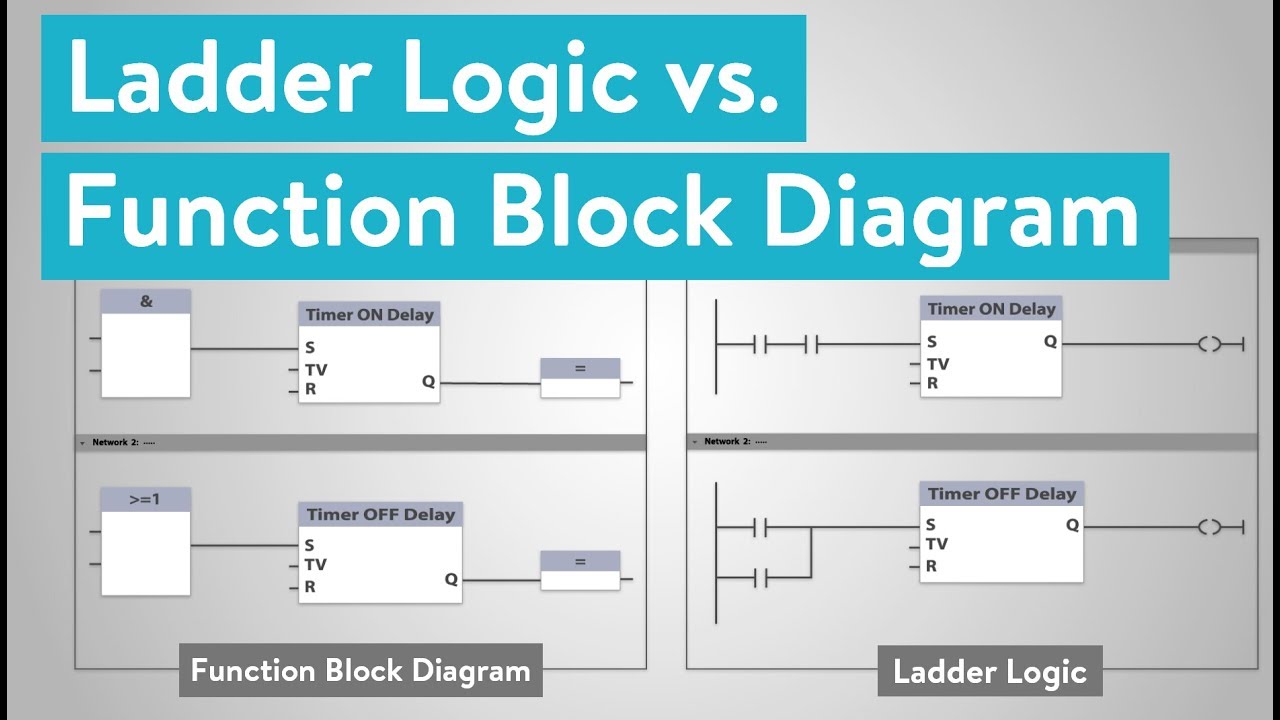
What is the Difference between Ladder Logic and Function Block Diagrams

PLC Experion programming code for FLC as functional block diagram

eBook: Automating Manufacturing Systems; with PLCs
